

IT departments are challenged with having to choose and configure data storage to meet present-day and future data center, system and end-user requirements for their organizations. They have to predict application use, workload sizes, performance needs and capacity expectations for years to come. Determining these requirements, and then implementing a storage strategy that meets these needs for today and tomorrow, is a tremendous undertaking for any IT department.
As technology evolves, upgrades to the storage system present another challenge to IT and are typically limited by the original hardwarepurchase. For example, if a SATA-based storage infrastructurehad been deployed, all hardware upgrades including the server backplane, storage controller and replacement drives would need to be SATA or possibly SAS-based. In order for storage to evolve to the next level, compute systems must be built to support required applications using current and future resources. If these objectives are achieved, the end result to IT can be significant relating to reductions in storage cost and system complexities.
With the advent of SFF-TA-1001 specification1(also known as U.3), the storage industry is moving closer to configuring storage for present-day and future application requirements. U.3 is a term that refers to compliance with the SFF-TA-1001 specification, which also requires compliance with the SFF-8639 Module specification2. Solutions which are based on U.3 could be achieved with a tri-mode configuration that utilizes a single backplane and controller, supporting all three drive interfaces (SAS, SATA and PCIe®from one server slot. Regardless of the interface, SAS and SATA SSDs and hard drives, as well as NVMe™SSDs, are interchangeable within U.3-based servers and can be used in the same physical slot. U.3 addresses a number of industry needs, all while protecting the initial storage investment.
Industry Challenge
Today’s server storage architectures are challenged in the way they accommodate mixed or tiered environments. Within any particular server, storage may require combinations of hard drives and SSDs configured with varied interfaces depending on the needs of the workload. For example, an engineering team may require fast NVMe drives to test code in their development environments. Another workgroup may require SAS drives to achieve high availability and fault tolerance for their revenue-generating database. And, another group may rely on capacity-optimized SATA drives or value SAS drives for analyzing cold data in real-time. Whatever the application is, portions of the server can be segmented to address the varied use cases.
Without U.3 from a server design perspective, OEMs need to develop multiple backplanes, mid-planes and controllers to accommodate all of the available drive interfaces, which creates a challenging abundance of SKUs and purchasing options for customers to choose from.
Drive consolidation took an initial step forward when the SAS interface enabled enterprise SATA SSDs and HDDs to connect to SAS backplanes, HBAs or RAID controllers. This capability continues today as most servers ship with SAS HBAs or RAID cards that enable SAS and SATA SSDs/HDDs to be used in the same drive bay. Though SATA drives can be easily swapped with SAS drives, there was no support for NVMe SSDs as they still required a separate configuration that utilizes an NVMe-enabled backplane (Figure 1).
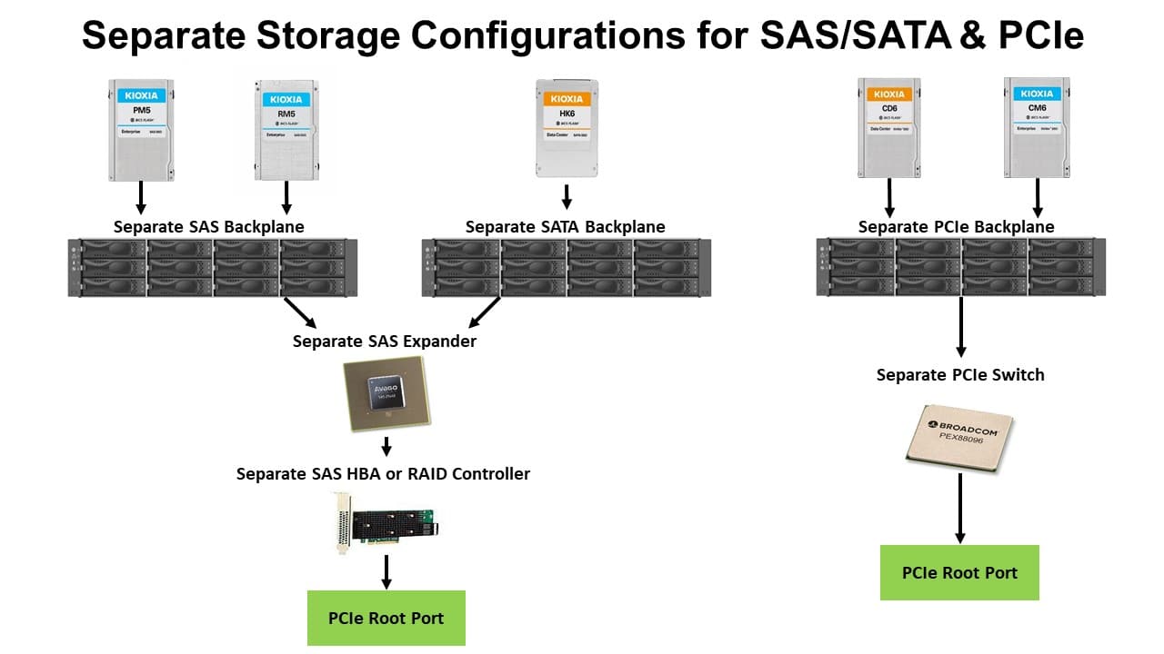
Figure 1 depicts separate backplanes required for SAS, SATA and PCIe interfaces
Support for NVMe SSDs as part of the drive consolidation strategy is extremely important as these deployments are on the rise due to the significant performance improvements they deliver over SAS and SATA SSDs. Unit consumption of NVMe SSDs in the enterprise (including both data center and enterprise versions) are expected to represent over 42.5% of all SSDs by the end of 20193. Unit consumption in the enterprise will increase to over 75% by the end of 2021, and over 91% by the end of 20233. At present, NVMe-based server, infrastructure and RAID controller options are in their early stages, requiring many data centers to continue using SAS-based RAID hardware to provide a mature, robust level of fault tolerance and performance. To migrate directly to NVMe storage will typically require the purchase of new NVMe-enabled servers that use an NVMe-specific backplane and controller.
The next step in supporting all three SSD protocols with one common infrastructure occurred with the availability of the SFF-8639 connector, in conjunction with the development of the SFF-8639 Module specification. This connector was designed to support up to four lanes of PCIe for NVMe SSDs, and up to two lanes for SAS/SATA HDDs or SSDs. Compliance with the SFF-8639 Module specification has been designated as U.2. The receptacle version of the SFF-8639 connector mounts on the server backplane, and although it supports all three drive interfaces, NVMe and SAS/SATA drives are not interchangeable unless the bay was provisioned for both. A separate NVMe-enabled backplane was still required to support NVMe SSDs.
Drive consolidation has now evolved to U.3 where SAS, SATA and NVMe drives are all supported through one SFF-8639 connector when used with a tri-mode backplane and controller (Figure 2), and are also compliant with the SFF-8639 Module specification (U.2). For this approach, the same 8639 connector is used except the high-speed lanes are remapped to support all three protocols. The U.3 specification includes the pinouts and usage for a multi-protocol accepting device connector, and was developed by the Storage Networking Industry Association (SNIA) SSD Form Factor (SFF) Technical Affiliate (TA). The specification was ratified in October 2017.
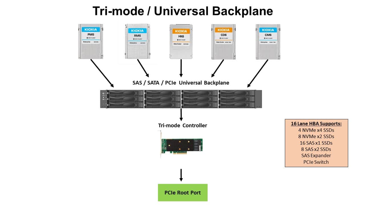
Figure 2 depicts the U.3 tri-mode universal storage configuration for SAS, SATA and PCIe interfaces
Key U.3 Components
The U.3 tri-mode platform can accommodate NVMe, SAS and SATA drives from the same server slot through a single backplane design and SFF-8639 connector with revised wiring as defined by the SFF-TA-1001 specification. The platform is comprised of a: (1) Tri-mode Controller; (2) SFF-8639 Connector (one for the drive and one for the backplane); and (3) Universal Backplane Management Framework.
Tri-Mode Controller
The tri-mode controller establishes connectivity between the host server and the drive backplane, supporting SAS, SATA and NVMe storage protocols. It features a storage processor, cache memory and an interface connection to the storage devices. The storage adapter supports all three interfaces, driving the electrical signals for the three protocols through a single physical connection. An ‘auto-sense’ capability within the controller determines which of the three interface protocols is currently being serviced by the controller.
From a design perspective, the tri-mode controller eliminates the need for OEMs to use one controller that is dedicated to SAS and SATA protocols, and a different controller for NVMe. It delivers simplified control that enables common bay support for SAS, SATA and NVMe drive protocols. With this flexibility, multiple drive types can be mixed and matched with SAS and SATA SSDs/HDDs, as well as NVMe SSDs.
SFF-8639 Connector
The SFF-8639 connector enables a given drive slot on the backplane to be wired to a single cable so it can provide access to a SAS, SATA or NVMe device, and determine the proper communications protocol driven by the tri-mode host. The SFF-TA-1001 (U.3) specification ties the components together by defining pin usage and slot detection, as well as addressing host and backplane wiring issues that occur when designing for a backplane receptacle that accepts both NVMe and SAS/SATA storage devices (Figure 3).
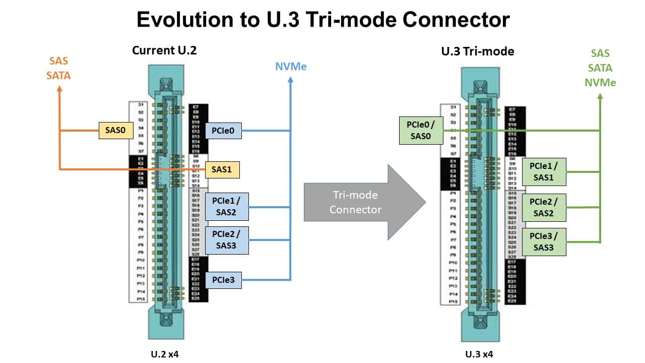
Figure 3 showcases the evolution to a U.3 tri-mode connector
The SFF-TA-1001 specification supports the three interface types on the SFF-8639 connector with signals for the host to identify its type, and with signals for the device to identify its configuration (e.g., dual-port PCIe).
U.3 eliminates the need for separate NVMe and SAS/SATA adapters, enabling OEMs to simplify their backplane designs with fewer traces, cables and connectors. This results in a cost benefit associated with building backplanes with fewer components, as well as an overall simplification of OEM server and component SKUs. Devices that are U.3-based are required to be backwards-compatible with U.2 hosts.
Universal Backplane Management Framework
The universal backplane management (UBM) framework defines and provides a common method for managing and controlling SAS, SATA and NVMe backplanes (Figure 4). It, too, was developed by the SSD Form Factor Working Group under the ratified specification SFF-TA-10054and provides an identical management framework across all server storage regardless of the interface protocol (SAS, SATA or NVMe) or the storage media (HDDs or SSDs).
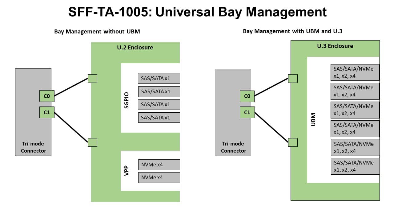
Figure 4 showcases only one domain required for U.3 backplane and bay management
Source: Broadcom® Inc.5
The management framework allows users to manage SAS, SATA and NVMe devices without any required changes to drivers or software stacks, and addresses a number of system-level tasks that are important to the NVMe protocol, and specifically to U.3 operation. This management includes the ability to:
- Provide exact chassis slot locations. For this capability, the UBM framework enables users to easily identify where storage drives that need to be replaced are located, or as it relates to troubleshooting, identifies possible issues that may be associated with drive slots, cables, power or the drives themselves.
- Enable cable installation order independence. To address this capability prior to the tri-mode configuration, users were required to lay specific cables to specific drive slots as overall cable length was extremely important in these configurations. In the tri-mode configuration, a multi-use cable is connected to all drive slots eliminating this issue.
- Manage LED patterns on the back-plane. The UBM framework enables users to utilize LED encoding on each drive that delivers a visible signal of drive activity that includes drive use, drive failures, power, etc.
- Enable power and environmental management. The UBM framework manages power to a slot and storage device with its main function to power cycle an unresponsive device.
- Enable PCIe resets. At the bus level, PCIe resets every device attached to a PCIe bridge regardless of whether the storage drives are functioning normally or not. The UBM framework enables users to activate PCIe resets on specific drive slots, resetting only the drives that need it.
- Enable clocking modes. With higher data rates delivered by PCIe 3.0 and PCIe 4.0, clocking becomes more difficult to support at these higher speeds. The UBM framework can configure storage devices to use either a traditional PCIe clock network or embed clock signals directly into the high-speed signals. Embedded clock signals can have a significant effect in reducing the electromagnetic interference associated with high-speed signaling, resulting in very flexible clocking.
The UBM framework enables a controller to dynamically divide the PCIe lanes by describing the backplane so U.3 x1, x2 and x4 wiring are all possible. It also provides a way to control the single PERST signal (PCIe reset) from other sideband signals (such as CLKREQ and WAKE) into multiple independent occurrences for 2×2 and 4×1 wiring. UBM also provides reference clock (REFCLK) control for 2×2 and 4×1 wiring. Though UBM is designed as a framework that can operate on its own, it unlocks the full power of U.3 when the UBM is implemented. The end result is a universal backplane management system that allows for greater configurability and true system flexibility.
U.3 Platform and SSD Availability
With the ratification of the SFF-TA-1001 specification, a U.3 ecosystem has evolved with leading server, controller and SSD vendors developing solutions to move this technology platform forward. For example, servers with tri-mode controllers, and associated backplanes, are being implemented by some tier 1 server OEMs. Initial system availability is expected to be through tier 1 and tier 2 server OEMs, followed by broad channel offerings.
From a controller perspective, most RAID/HBA vendors are developing controllers with tri-mode capabilities and support for U.3 operation.
From an SSD perspective, four drive vendors, KIOXIA (formerly Toshiba Memory), Samsung, Seagate and SK Hynix successfully participated in the first U.3 Plugfest in July 2019 held at the University of New Hampshire’s Interoperability Lab. Of these SSD vendors, KIOXIA was the first to demonstrate SFF-TA-1001 (U.3) SSDs at Flash Memory Summit 2019.
Summary
With big data getting bigger and fast data getting faster, coupled with computational-intensive applications, like artificial intelligence, machine learning and even cold data analysis, the need for higher performance in data storage is growing by leaps and bounds. Having to predict today’s application use, workload sizes, performance needs and capacity expectations is quite the challenge, but forecasting use for years to come takes the challenge to a new level.
The U.3 tri-mode approach builds on the U.2 specification using the same SFF-8639 connector. This approach combines SAS, SATA and NVMe support into a single controller inside of a server, managed by a UBM system that allows SAS SSDs/HDDs, SATA SSDs/HDDs and NVMe SSDs to be mixed and matched. U.3 provides a tremendous array of benefits that include:
- Single backplane, connector and controller for storage
- Eliminates separate components for each supported protocol
- Enables hot-swapping between devices (if the device supports it)
- Provides SAS/SATA/NVMe support from one drive slot
- Lowers overall storage costs by using less cabling, fewer traces and fewer components
- Delivers greater storage configurability and true system flexibility
- High Performance
- Delivers 64% greater drive bay bandwidth and IOPS performance when a SATA SSD is replaced by a NVMe/PCIe Gen3 x1 SSD in a U.3 drive bay6
- Delivers 13x bay capability performance improvement when a SATA SSD is replaced by a NVMe/PCIe Gen4 x4 SSD in a U.3 drive bay given throughput of SATA = 0.6GB/s; x1 PCIe Gen3 NVMe = 0.98GB/s; and PCIe Gen4 NVMe x4 = 7.76GB/s6
- Management
- Provides the same management tools across all server storage protocols via UBM
- Universal Connectivity
- Extends the connectivity benefits of SAS and SATA to NVMe
- Eliminates the need for protocol-specific adapters
- Enables U.2- (SFF-8639 Module) or U.3- (SFF-TA-1001) compliant drives to be used in the same storage architecture
- Lowers system cost through a universal backplane and shared cabling infrastructure
- Lowers system purchase complexity (removes the possibility of selecting the ‘wrong’ backplane and storage adapters
The U.3 platform addresses a number of industry needs: reducing TCO expenditures, reducing the complexities of storage deployments, providing a viable replacement path between SATA, SAS and NVMe, maintaining backwards compatibility with current U.2 NVMe-based platforms, all while protecting the customer’s initial storage investment.
About the Authors:
| John Geldman is the Director of SSD Industry Standards at KIOXIA America, Inc. (formerly Toshiba Memory America, Inc.) and leads the storage standards activities. He is currently involved in standards activities involving JEDEC, NVM Express, PCI-SIG, SATA, SFF, SNIA, T10, T13 and TCG. He has been contributing to standards activities for over three decades covering NAND flash memory, hard drive storage, Linux™, networking, security, and IC development. John has been on the board, officered, chaired or edited specifications for CompactFlash, the SD Card Association, USB, UFSA, IEEE 1667, JEDEC, T10, and T13, and currently serves as a member of the Board of Directors for NVM Express, Inc. |

John Geldman, KIOXIA
| Rick Kutcipal is a Marketing Manager in the Data Center Storage Group at Broadcom Inc., and is a 25-year computer and data storage business veteran. He coordinates the majority of global storage standards activities for Broadcom. Prior to Broadcom, Rick spent nearly 15 years at LSI Logic as a product manager and was instrumental in launching the first 12Gb/s SAS expander in the industry. Earlier in his career, Rick designed advanced chips and board level systems for Evans & Sutherland. Today, Rick serves on the Board of Directors of the SCSI Trade Association (STA), playing an influential role in defining and promoting SAS technology. |

Rick Kutcipal, Broadcom
| Cameron Brett is the Director of Enterprise Marketing at KIOXIA America, Inc. (formerly Toshiba Memory America, Inc.) and is responsible for the outbound marketing and messaging of enterprise SSD, software and memory products. He represents KIOXIA as co-chair of the NVM Express marketing workgroup, also as a Board of Directors member and president of the SCSI Trade Association (STA), and also as co-chair of the Storage Networking Industry Association (SNIA) SSD SIG. Cam is a 20-year veteran of the storage industry and has held previous product marketing and management positions with Toshiba Memory, PMC-Sierra, QLogic, Broadcom and Adaptec. |

Cameron Brett, KIOXIA
Trademarks:
Broadcom is a registered trademark of Broadcom Inc. Linux is a trademark of Linus Torvalds. NVMe and NVM Express are trademarks of NVM Express, Inc. PCIe is a registered trademark of PCI-SIG. SCSI is a trademark of SCSI, LLC. All other trademarks or registered trademarks are the property of their respective owners.
Notes:
1The SFF-TA-1001 Universal x4 Link Definition specification for SFF-8639 is available at: http://www.snia.org/sff/specifications.
2The SFF-8639 Module specification is available at: http://www.pcisig.com/specifications.
3 Source: IDC. – “Worldwide Solid State Drive Forecast Update, 2019-2023, Market Forecast Table 12, Jeff Janukowicz, December 2019, IDC #44492119.
4The SFF-TA-1005 Universal Backplane Management (UBM) specification is available at: http://www.snia.org/sff/specifications.
5Source: Broadcom Inc. – “Common Method for Management of SAS, SATA and NVMe Drive Bays – SFF-TA-1005 a.k.a. UBM: Universal Bay Management.”
6The performance numbers represent the physical capabilities of the interface running across the connector and does not represent the capabilities of the host bus adapter or the storage device.
Product Image Credits:
Figure 1: Separate Storage Configurations for SAS/SATA and PCIe:
- SAS Expander: Source = Avago Technologies – Avago Technologies 12Gb/s SAS expander, SAS35x48
- SAS HBA: Source = Broadcom Inc. – Broadcom 9400-8i SAS 12Gb/s host bus adapter
- PCIe Switch: Source = Broadcom Inc. – Broadcom PEX88096 PCIe storage switch
- SSDs: Source = KIOXIA America, Inc. – PM5 12Gbps enterprise SAS SSD, RM5 12Gbps value SAS SSD, HK6 enterprise SATA SSD, CM6 PCIe 4.0 enterprise NVMe SSD and CD6 PCIe 4.0 data center NVMe SSD
Figure 2: Tri-mode / Universal Backplane:
- Tri-mode Controller: Source = Broadcom Inc. — Broadcom 9400-16i tri-mode storage adapter
- SSDs: Source = KIOXIA America, Inc. – PM5 12Gbps enterprise SAS SSD, RM5 12Gbps value SAS SSD, HK6 enterprise SATA SSD, CM6 PCIe 4.0 enterprise NVMe SSD and CD6 PCIe 4.0 data center NVMe SSD


 Amazon